Understanding Basic Components of a Natural Gas Plant: Natural Gas Plant Drawing Easy

Natural gas plant drawing easy – Natural gas power plants convert the chemical energy stored in natural gas into electricity, a vital process in modern energy grids. These plants, while varying in complexity, share fundamental components working in concert to achieve this energy transformation. Understanding these components is key to appreciating the efficiency and environmental impact of natural gas power generation.
Simplified Natural Gas Plant Diagram and Component Functions
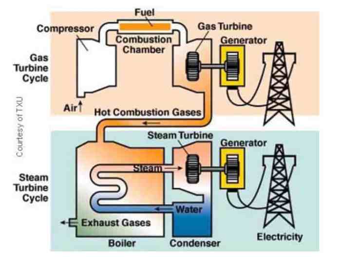
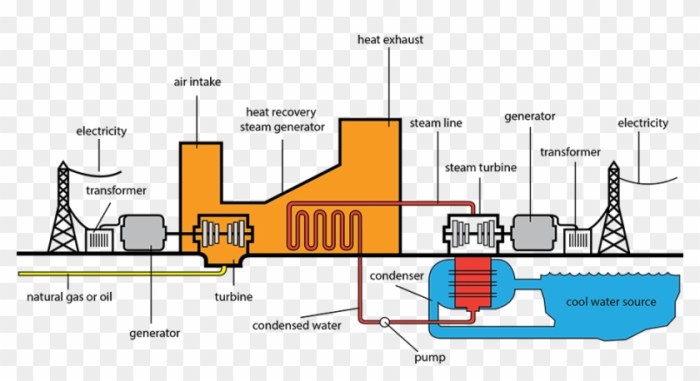
A simplified natural gas power plant can be visualized as a series of interconnected stages. Natural gas, primarily composed of methane, enters the plant and undergoes several transformations before generating electricity. The main components include: a gas turbine, a heat recovery steam generator (HRSG), and a steam turbine connected to a generator. The gas turbine combusts the natural gas, expanding hot gases that spin a turbine, producing mechanical energy.
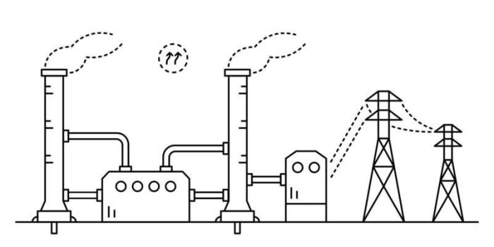
Sketching a natural gas plant can be surprisingly simple! Start with basic shapes, focusing on the main structures. Think about the perspective – maybe you need to add some supporting elements, like a pathway, and for that, check out this helpful guide on easy drawing of a set of stairs – it’s all about mastering basic shapes and lines! Then, apply that same principle back to your natural gas plant drawing, adding details to make it really pop.
This high-temperature exhaust gas then flows into the HRSG, generating steam. This steam drives a second turbine, a steam turbine, further increasing efficiency. Finally, both turbines drive generators to produce electricity. This combined cycle approach maximizes the energy extracted from the fuel.
Labeled Diagram of Natural Gas Flow
Imagine a diagram showing the flow of natural gas. First, the natural gas enters the plant through a pipeline and is filtered to remove impurities. Next, it proceeds to the combustion chamber of the gas turbine. The combustion process produces high-pressure, high-temperature gases that drive the gas turbine. The exhaust gases from the gas turbine are then channeled to the heat recovery steam generator (HRSG).
In the HRSG, the heat from the exhaust gases is used to generate steam. This steam then flows to the steam turbine, which spins to generate additional electricity. Finally, the spent steam is condensed and recycled, while the generated electricity is fed into the power grid. The diagram would visually represent this sequential flow, clearly indicating the transfer of energy at each stage.
Comparison of Natural Gas Power Plant Types
Different types of natural gas power plants exist, each with varying levels of efficiency, emissions, and size. The following table provides a comparison:
| Plant Type | Efficiency | Emissions | Size (MW) |
|---|---|---|---|
| Open-cycle gas turbine | 30-40% | High NOx, CO2 | 50-300 |
| Combined cycle | 50-60% | Lower NOx, CO2 than open cycle | 100-500+ |
| Integrated gasification combined cycle (IGCC) | 55-65% | Lower NOx, CO2, potential for CO2 capture | 500+ |
| Aeroderivative gas turbine | 30-40% | Similar to open cycle | 20-100 |
Advanced Diagram Features (Optional)

Elevating the schematic representation of a natural gas plant beyond basic components requires incorporating nuanced details reflecting operational realities and potential challenges. This involves integrating environmental considerations, providing a detailed visualization of core machinery, and showcasing crucial safety mechanisms. Such enhancements foster a more comprehensive understanding of the plant’s function and its integration within a larger context.
Detailed diagrams can significantly improve communication and analysis. By visually representing complex processes and potential hazards, these diagrams aid in risk assessment, operational planning, and environmental impact evaluation. They are invaluable tools for engineers, operators, and regulatory bodies alike.
Environmental Impact Considerations in Diagrams
Illustrating environmental impact within the diagram can be achieved through various visual cues. For example, the emission points of the plant could be clearly marked, with arrows indicating the direction of exhaust gases. These arrows could be color-coded to represent different pollutants, such as carbon dioxide (CO2) depicted in grey, nitrogen oxides (NOx) in brown, and methane (CH4) in light blue.
A separate legend could explain the color-coding system, providing quantitative data on emission rates or estimated amounts per year. Additionally, a visual representation of nearby water bodies and their potential interaction with the plant’s cooling system, indicated by blue lines representing water flow, could further contextualize the plant’s environmental footprint. The use of a separate, smaller inset map showing the location of the plant within a larger ecological area could offer broader perspective on its environmental context.
Gas Turbine and Generator Representation, Natural gas plant drawing easy
A detailed depiction of the gas turbine and generator is crucial for a comprehensive diagram. The gas turbine itself can be represented as a stylized cutaway view, showcasing the compressor, combustor, and turbine sections. Different colors could highlight the flow of compressed air, fuel, and exhaust gases. The generator can be depicted as a separate component connected to the turbine shaft, clearly showing the energy transfer mechanism.
This could include simple symbols for electrical connections leading to the power grid, represented by thick black lines. Adding numerical data on power output (e.g., megawatts) alongside the generator symbol enhances the diagram’s informational value. Furthermore, a simplified schematic of the generator’s internal workings, showing the stator and rotor, can be included as an inset to further clarify the energy conversion process.
Safety Feature Representation
Safety features should be prominently displayed. These could include visual representations of fire suppression systems (e.g., sprinklers, fire extinguishers) denoted by red symbols. Pressure relief valves, essential for preventing catastrophic pressure buildup, could be represented by symbols indicating pressure release mechanisms. Emergency shutdown systems, including their activation points, should be visually distinct. Clearly marked emergency exits and escape routes, represented by green arrows and highlighted pathways, should also be incorporated.
Furthermore, the locations of safety equipment, such as gas detectors, could be marked with corresponding symbols and potentially linked to a centralized control room indicated by a separate symbol.
Methods for Depicting Energy Flow
Understanding the various methods for visually representing energy flow is essential for creating a clear and informative diagram. Different methods offer unique advantages and disadvantages.
| Method | Advantages | Disadvantages | Example |
|---|---|---|---|
| Colored Arrows | Simple, intuitive, easily understood. | Can become cluttered with multiple flows. | Thick blue arrows representing natural gas flow from the pipeline to the plant. |
| Flowcharts | Clearly shows the sequence of energy transformations. | Can be complex for large systems. | A series of boxes representing different stages, connected by arrows indicating the direction of energy flow, from combustion to electricity generation. |
| Sankey Diagrams | Visually represents the magnitude of energy flows. | Requires specific software for creation. | A diagram where the width of the arrows corresponds to the amount of energy flowing through each stage, showcasing energy losses at each stage. |
| Thermodynamic Diagrams | Provides detailed thermodynamic data. | Requires specialized knowledge to interpret. | A pressure-volume diagram illustrating the thermodynamic cycles of the gas turbine. |
Creating a Step-by-Step Guide for Drawing

This section provides a beginner-friendly, step-by-step guide to drawing a simplified representation of a natural gas plant. The process focuses on conveying the key components and their relationships, rather than precise architectural detail. This method is ideal for understanding the basic layout and functionality of such a facility.
Materials and Tools
Creating a clear and informative drawing requires the right tools. A pencil (preferably a 2H or HB for easy erasure and clear lines), a ruler, an eraser, and a sheet of paper are essential. Colored pencils or markers can enhance the drawing by differentiating components. For a more refined presentation, consider using a fine-liner pen for outlining after the initial pencil sketch.
A compass might be helpful for drawing perfectly round components like tanks.
Step-by-Step Drawing Process
This process simplifies the representation of a natural gas plant, focusing on its key functional areas.
- Step 1: The Main Building. Draw a large rectangle to represent the main processing building. This rectangle should be approximately twice as wide as it is tall, with slightly rounded corners to suggest a more modern industrial design. The size is arbitrary; adjust to fit your paper.
- Step 2: Gas Wells Representation. To the left of the main building, draw several small circles connected by thin lines representing pipelines bringing gas from the wellheads. These lines should converge towards the main building. The circles represent simplified wellhead structures. Vary the sizes slightly for a more realistic representation.
- Step 3: Gas Treatment Units. Within the main building, draw several smaller rectangles of varying sizes to depict the different gas treatment units. These rectangles can be arranged in a logical flow, suggesting a processing sequence. Label these units with simple notations such as “Dehydration,” “Compression,” and “Purification”.
- Step 4: Storage Tanks. To the right of the main building, draw two or three large cylinders to represent gas storage tanks. These should be noticeably larger than the gas treatment units within the main building. Indicate the height and diameter of the tanks using a scale, if desired.
- Step 5: Pipeline Connections. Draw thick lines connecting the gas wells to the main building and the main building to the storage tanks. These lines represent pipelines, and their thickness should reflect the scale of the gas flow. Use arrows to indicate the direction of gas flow.
- Step 6: Power Generation (Optional). If your drawing includes power generation, add a smaller rectangular structure near the storage tanks, labeling it “Power Generation”. You can add a simple symbol, such as a lightning bolt, to further clarify its function.
- Step 7: Final Touches. Lightly erase any unnecessary pencil lines. Using a fine-liner pen, carefully Artikel the shapes. Add color to distinguish different components; for instance, use different shades of green for pipelines and brown for the main building.
Checklist of Elements
Before considering the drawing complete, review this checklist to ensure all key elements are included and clearly represented. This aids in creating a comprehensive and easily understandable diagram.
- Main Processing Building: A large rectangle representing the central processing facility.
- Gas Wells: Several small circles connected by lines representing pipelines.
- Gas Treatment Units: Smaller rectangles within the main building, labeled appropriately.
- Storage Tanks: Large cylinders representing gas storage.
- Pipelines: Thick lines connecting the wells, processing building, and storage tanks.
- Arrows indicating gas flow direction on pipelines.
- (Optional) Power Generation Unit: A separate structure representing power generation.
Helpful Answers
What software can I use to create these drawings?
Many programs work well! Simple drawings can be done with pencil and paper. For digital diagrams, consider programs like Visio, Lucidchart, or even PowerPoint.
How important is scale in my drawing?
For simplified diagrams, precise scale isn’t crucial. Focus on clearly representing the relative sizes and relationships between components.
Are there online resources for pre-made templates?
While less common for highly simplified diagrams, you might find some basic templates online through educational resources or engineering websites. It’s often easier to create your own from scratch for maximum customization.
